“ After so many years of touch sensors, this time someone decided to change the bottom line of logic: not on electrons, but on ions.
Pressure resistance, voltage, capacitance, and friction voltage are the four technical routes used by the vast majority of touch sensors today. They all have advantages, but one thing is common: the nature of the signal is the transport of electrons.
This is not the way the human body works. The mechanical sensors in the skin, which convert the shape into an electrical signal, are the input of the ion: the mechanical gate control ion channels open, the ion flows in, the membrane voltage rises, and the more the valve is passed, the more it emits the electrical current, which is sent to the central nervous system.
This "physical underpinning" may be one of the reasons why artificial touch is so late that it can't really replicate human touch. For rehabilitation robots, active limbs, and next-generation machine interfaces, genuinely credible touch feedback is precisely the most critical part of the complex operation, the "body sense" of safe human interaction with artificial limbs.
Now, a research team from the University of Aarhus, Denmark, has proposed a new concept of an artificial ion mechanical sensor, the Artificial Ionic Mechanoreceptor (AIM), which has recently been featured in the Advanced Functional Materials series.
Its core is simple: a microflow filled with a NaCl solution, which is pressed to create a voltage of its own.

01.
The human body uses ions to transmit signals, and the sensors do the same.
Let's take a look at the prototype.
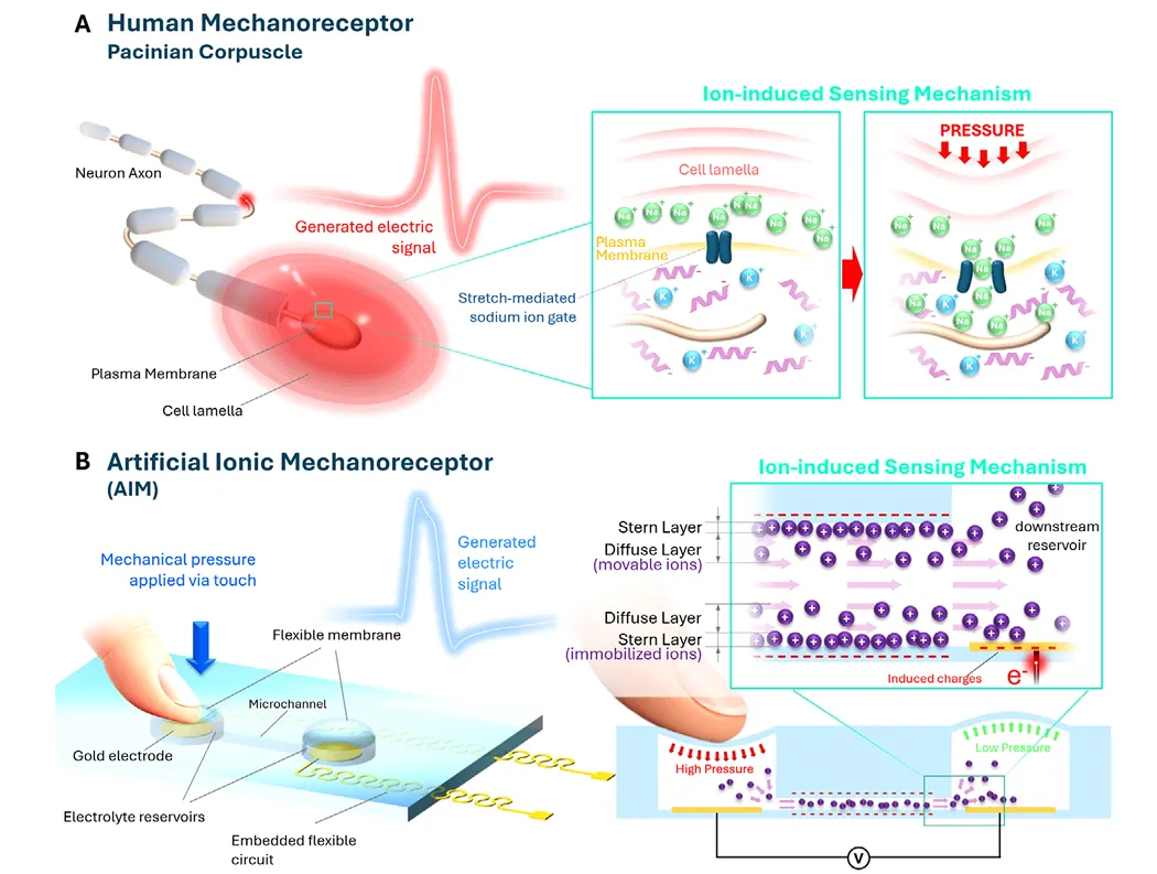
The team referred to the Pacinian corpuscle, a rapidly adaptive sensor located deep below the skin that senses high-frequency vibration. It is shaped like an onion: a layered structure envelops the central neural tube, which is filled with NaCl-rich extracellular fluid, while the inner membrane of the neural tube is composed of lithium ions and negatively charged proteins.
Because of this ion distribution, the voltage inside and outside the membrane at rest is −70 mV. The stretch door control channel on the membrane is closed at this time. Once mechanical stimulation, the deformation of the plate layer transmits pressure to the membrane, the ion channel is pulled, and the ion flows in a smooth electrochemical gradient, and the voltage around the neural end of the membrane increases dramatically as the voltage exceeds −50 mV. The voltage of motion is generated, sending a signal to the brain, which then pulls the cells back into a still state.
The structure is complex, but the principle can be summarized in one sentence: mechanical disruption is used to change the distribution of ions, thereby changing the rate of current.
The AIM was designed based on the phrase: two electrolytic fluid storage cavities embedded in a flexible elastic body, connected in the middle by a microchannel, complete with NaCl solution, and the top of each storage cavity is sealed by a thin layer of PDMS membrane, which is responsible for "receiving touch".
The key is in the interface. The PDMS surface itself carries electricity, thus forming a bi-electric layer (EDL) near the wall of the conduit, where the ion distribution becomes uneven and divides into two parts: the tight-fitting wall surface, the tightly bonded and essentially stationary Stern layer, and the weak external static electrical action, the diffuse layer where the ion can still move freely.
Press one side of the film, the liquid inside the cavity is pressurized, and the pressure difference between the two cavities occurs, and the electrolyte flows along the microfluidic pathway. The flowing liquid "cuts" the two electrodes together, pulling the anti-ions that can move in the diffuse layer together, forming a flowing current; the ions accumulate in the lateral cavity, and the bottom metal electrode reads the electrode transformation matrix, which is the flowing potential. Following the classic Helmholtz hypothesis of Smoluchowski, the size depends on the surface charge density, the flow rate, the concentration and the flow rate of the ions.
After loosening, the membrane topped on the other side pushes the fluid back with its own elasticity, causing a reverse flow in the conduit, followed by a reverse signal.
The whole process does not require any additional voltage or incentive sources, and is a complete self-supply of energy sensing.
02.
442.5 Hz、5 mM、0.05 mV/g
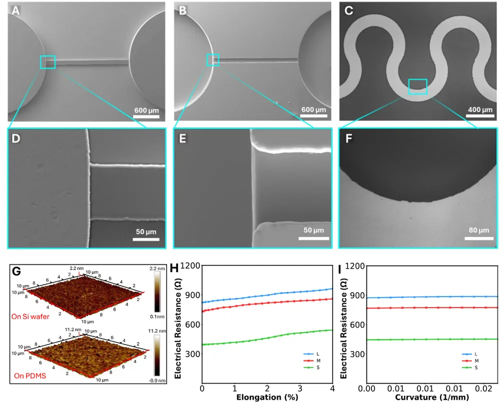
The device is made of soft light engraving: the bottom is a prototyped metal electrode of about 100 μm thick PDMS film (electron beam distilled about 45 nm, detected about 429 Å), the top is mated with a mother mold of two-step SU-8 light engraving, for the storage of fluid cavities, micro channels and syringe mouths, and for the activation binding of carbon monoxide atoms by HMDS. Finally, the entire device is about 400 μm thick.
The results showed that the SU-8 mother model had a size error of about 0.5%; the surface roughness was about 15 nm; and the PDMS replica had a size deviation of less than 1%. In electromagnetic terms, the team tested three serpentine lines: three pattern resistors rose gradually under 4% stretch stress, but no cracks or breakage, and the resistance variations in the bending test were less than 1.5%, and the S type was eventually selected with a lower initial resistance.
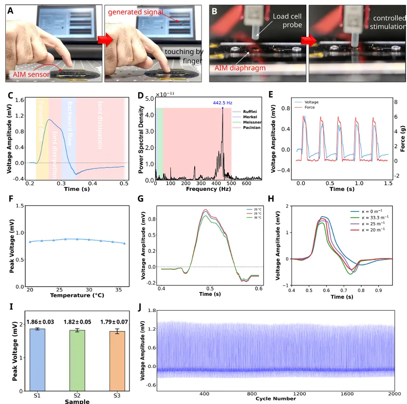
When the probe is pressed down, the conduit produces a direct flow, and the signal rises to a peak; the probe remains stationary for about 50 ms, with virtually no flow in the conduit, but the signal decreases slowly because the ions accumulated near the electrode are spreading back into equilibrium; the probe is raised, and the reverse flow strongly disrupts the distribution of the remaining ions, the voltage decreases rapidly and there is a negative "downward shock" (undershoot); finally the liquid stops, the ions are re-harmonized, and the signal slowly returns to the baseline.
This two-phase waveform, first surging, then surging, and finally turning to zero, is very similar in logic to the instantaneous response of rapidly adapting biomechanical sensors: "contact begins" with sharp surge markings, "contact ends" with surge and recovery markings, thus clearly separating successive stimulation events over time.
For the typical waveform as FFT, the main peak occurs at about 442.5 Hz and falls well within the working frequency of the vibration-sensitive Pasini sensor.
In terms of stability: 2000 consecutive loads under Hz, the output remains stable, the relative standard deviation between cycles is about 3.4%, and the thin film structure is not seen to fail; overall output stability in the range of 20 Hz to 36 °C, the signal changes by about 6% when heated to 28 °C, and then slightly decreases; when curved on cylinder supports of different diameters, the uptrend, peak, thrust, and recovery characteristics are essentially preserved. In addition, the device under the cycle stimulation has a working frequency window: the signal below about 0.5 Hz is too weak to be detected reliably, and at about 7 Hz it becomes unstable due to the lack of ion redistribution. This is similar to the behavior of the silicon that is required by biological sensors to complete the "non-load period".
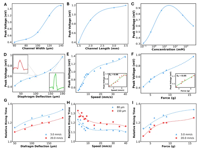
The flow rate increases with peak voltage of 60→140 μm, but slows when approaching 140 μm; the flow rate increases with peak voltage of 1.5→3.5 mm, which tends to slow near 3.0 mm.
More ions, more carrier currents, and more current are expected to increase; however, increased concentrations will significantly decrease the zeta voltage; the diffusion layer is pressurized by thin silicon at a single electrolyte estimate of 0.1 mM, 0.5 mM, 5 mM, 0.5 M, 5 M corresponding deby lengths of about 30.4, 13.6, 4.3, 0.43 and 0.14 nm respectively.
In the stimulus parameters, the pressure depth of the film increases from 30 μm to 190 μm, and the peak voltage increases with it and responds faster; the probe speed is nearly linear in the 2×10 mm/s range, the velocity sensitivity is about 0.06 mV/mm, the force sensitivity is about 0.05 mV/g; the higher the speed, the faster the flow, the faster the ion near the electrode is "squeezed out" and the increase slows down.
03.
It's the first time I've ever had a pulse in my fingers.
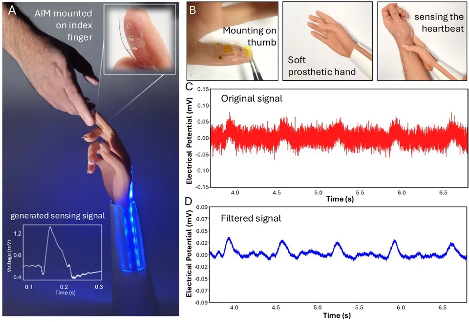
In the Concept Verification section, the researchers attached the AIM to a soft limb.
Installed at the tips of the thumb, it produces a clearly readable signal when in contact with the human finger; instead of the thumb, it successfully captures the cyclic pulse wave shape by pressing the artery at the wrist.
This is the most demanding test scenario of all time, providing the weakest mechanical stimulus and the smallest output signal. The signal noise ratio of the original signal was about 2.2 and increased to about 8 after conventional signal processing and retained the pulse waveform to reliably identify the physiological signal.
However, although the shape of the waveform is already very similar to a biological sensor, the voltage range is not enough to capture the current output of neuron stimulation thresholds that have not yet reached about 20 mV. If you want to communicate directly with the nervous system, either externally amplify or from the device itself, the direction given by the team is to make surface chemistry modifications to the walls of the microcircuits, improve the surface charge density, and improve the zeta voltage and flow rate.
In the long run, the mechanism of "pressure-driven ion redistribution" and the mainstream solid-state transducers take a completely different path. It is self-sufficient, naturally compatible with soft materials, sensitive to weak stimuli, and the researchers believe that in addition to the fingertips of the prosthetic limbs, it also has the potential to extend to distributed artificial skin, pressure sensors that can be implanted, and scenarios such as neural tube robot hybrid interfaces, where chemical and ionic compatibility with biological tissue is crucial.
Address of the paper: