Hole holes are common and important characteristic information in metal parts and play a decisive role in the production and assembly of products. The method of reconstructing three-dimensional curves based on passive binocular vision has been widely used in the measurement of holes due to its high accuracy and robustness. The method can obtain size data such as diameter, center of the cylinder, but there are still problems in terms of measurement accuracy and completeness, and it is difficult to accurately measure deformed holes. To address these problems, a method of reconstructing three-dimensional curves based on linear projection has been proposed. The method will move the curve line of the cylinder to the surrounding area twice equidistantly, based on the three-dimensional reconstruction of the cylinder, and based on the three-dimensional reconstruction of the three-dimensional shape of the three-dimensional curves proposed by the previous two methods.
1 Quotes
Aluminum parts are widely used in automotive transportation, aerospace, etc. due to their excellent performance, such as their low density, high strength, and good finishing ability. Hole rolling information is a common and important characteristic of aluminum parts, requiring three-dimensional measurements to ensure finishing quality and product safety performance. Existing three-dimensional rotor measurement methods are mainly divided into two types: 1) rotor reconstruction based on measurement points. This method uses structural light technologies to first reconstruct the complete three-dimensional shape of the metal parts, and then to extract the rotor from the point cloud. 2) Rotor reconstruction based on passive binocular vision. This method directly rotates, matches and reconstructs the rotor on the image of the binocular camera.
To address these problems, the researchers attempted to improve the accuracy of contour extraction and triangular matching. Xie and others used image contours of round holes based on the Zernike matrix to obtain the optimum porosity of the holes. This method overcame the effect of part thickness, and reconstructed the point cloud of the round holes. Hu and others solved the problem of finding three contours of the right side of the camera based on the contours of the camera graphs, and then based on these reverse matrix proofs of the correctness of the error, to determine the existence of an effective method for matching the thickness of the graphs of the graphs of the graphs of the two holes. 3) Current research focuses mainly on round hole contours, which require elliptical adaptation to improve accuracy, making it difficult to use an isomorphic hole.
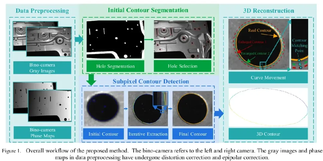
To address these problems, a three-dimensional contour measurement method based on strip projection was proposed. This method does not directly reconstruct three-dimensional contours from detected two-dimensional contours, but is calculated in reverse based on two curve movements. Based on this, the contours that need to be reconstructed are not at the edge of the hole. Therefore, phase matching can be used to ensure the accuracy of the reconstruction and the completeness of the upper and lower edges.
The remainder of this article is organized as follows: Section 2 outlines the specific implementation method; Section 3 gives experimental results to verify the performance of the method; and Section 4 summarizes this article.
2 Reconstruction of the three-dimensional contour
The overall workflow of the three-dimensional contour reconstruction is shown in Figure 1. The method consists of four parts. First, to obtain a graph and graph of the image on the left side of the camera, and to perform variation correction and polarity correction. Second, to achieve the initial partitioning and identification of the holes based on information such as the intensity, size of the holes. Then, to divide each hole to extract the pixel contour. Lastly, to rebuild the three-dimensional contour based on the two-curve movement reverses to calculate the true three-dimensional contour.
2.1 Pre-processing of data
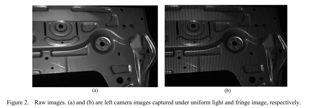
As mentioned above, the first step is to obtain a double-eyed camera gray image under uniform lighting in preparation for outline extraction, as shown in Figure 2 (a).
This includes the phase value, the intensity of the image under projection for the first image of the strip, the phase volume, the phase step number, and the substrate for the pixel in the image. Lastly, according to the pre-labelled camera parameters, the gradient correction and polarity correction are performed on the gray graph and the phase graph.
2.2 Initial layout split
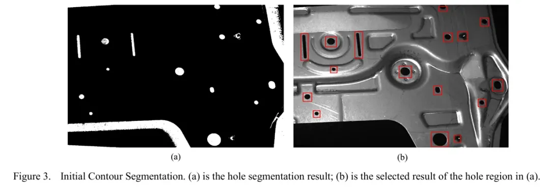
In order to ensure the accuracy and stability of sub-pixel outputs, the initial position of the hole outputs must first be determined. Thus, using the Otsu algorithm, the initial partition of the hole area is automatically achieved, as shown in Figure 3 (a).
2.3 Sub-pixel outline testing
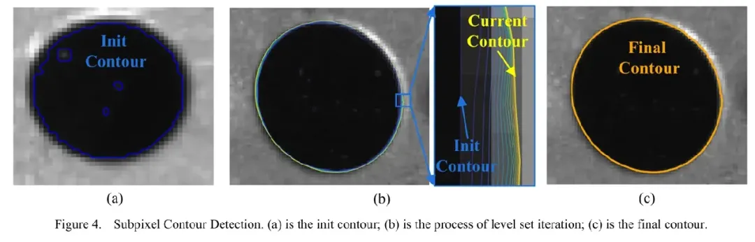
In order to ensure the accuracy of the extraction, each hole outline is extracted separately and operated in parallel. In addition, the subpixel outline is extracted using a horizontal aggregation algorithm that combines local intensity and overall intensity to represent:
For the local energy, for the global energy, for the corresponding weighting coefficients, for the gray image, for the smooth Heviside function of the horizontal cluster function, the parameters are, and, respectively, the average intensity within the local area and, respectively, the average intensity outside the global area.
2.4 Three-dimensional reconstruction
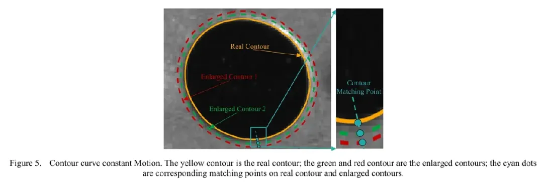
However, due to the thickness of the aluminum foil, the outputs taken from different angles would be inconsistent, causing the outputs to be reconstructed incorrectly. At the same time, due to too many candidates, the upper and lower edges are also prone to be reconstructed incorrectly. Therefore, we move two equal distances around the actual outputs to obtain two enlarged outputs, as shown in Figure 5.
It is important to note that the calculation method vector needs to sample the contour points to ensure that the distance between adjacent points is consistent. Then, the three-dimensional point cloud of the extended contour is reconstructed according to the phase matching. Due to the better quality of the phase at the extended contour, good quality contour point clouds can be obtained. Lastly, the corresponding contour point cloud is reconstructed in reverse according to the first two reconstruction contours.
These are real three-dimensional routing points, and three-dimensional points that are rebuilt according to moving constants and after moving, respectively.
3 Experiments
To verify the performance of the method, we experimented with a measurement system consisting of two CCD cameras (BFLY-U3-23S6M-C, 16mm lens, ML-M1618HR) and a digital light-processing projector (DLP4500).
3.1 Reconstruction of the three-dimensional hole layout
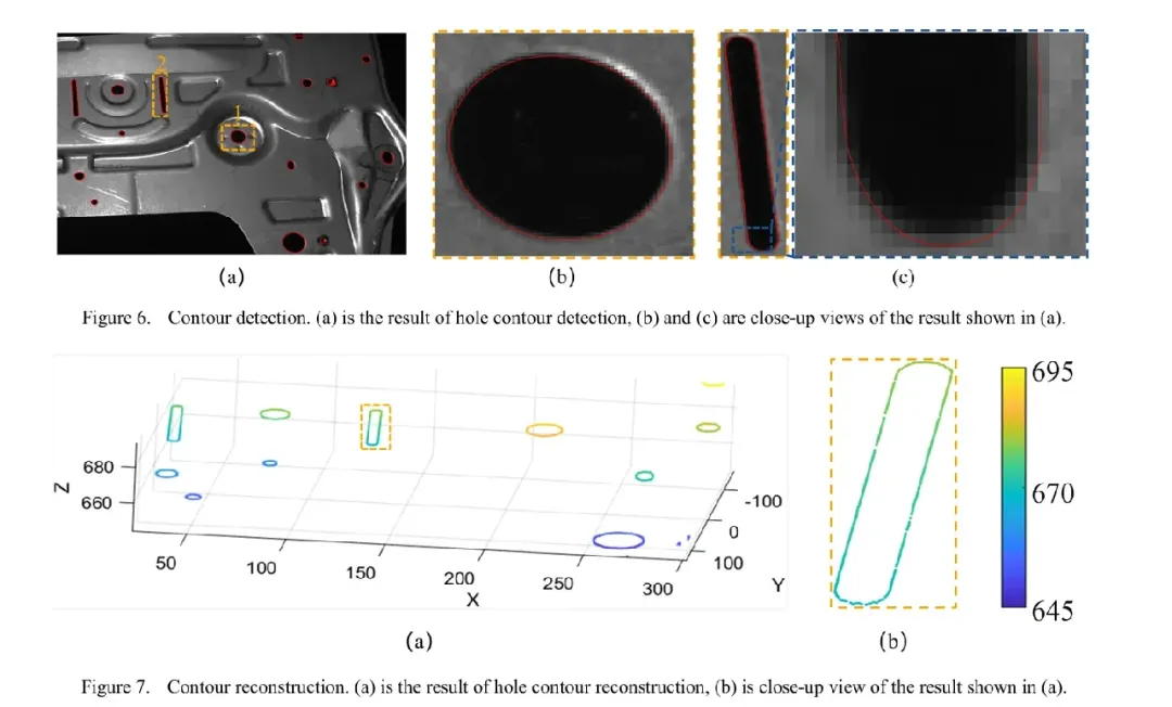
To verify the effect of this method, we measured the three-dimensional holes in a metal part of an automobile (the underside of the engine rack). The results of the test were shown in Figure 6. It was shown that the method was able to accurately extract various shapes of the holes.
3.2 Accuracy assessment
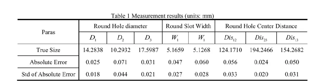
To evaluate the accuracy of the method, the Optiv Performance three-coordinate measuring machine (Optiv ADVANCE 452) is used to measure the real size of the hole, as shown in Figure 8.Table 1: The measurement result table contains the true dimensions of the diameter of the round hole D1, D2, D3, the width of the round hole W1, W2, the center of the round hole Dis12, Dis23, Dis13, absolute errors and standard deviationsThis means that the average absolute error between the center distance and the outline size obtained by this method does not exceed and.
4 Conclusions
In summary, this article proposes a three-dimensional contour measurement method based on strip projection of metallic pores. This method introduces phase information into contour matching points, improving the accuracy of matching, and reducing the impact of contour extraction inconsistencies on the left and right sides. In addition, this method can achieve the complete three-dimensional contour reconstruction of various shapes of pores.
This article is for academic sharing only. If there is an infringement, please contact the deleted text.