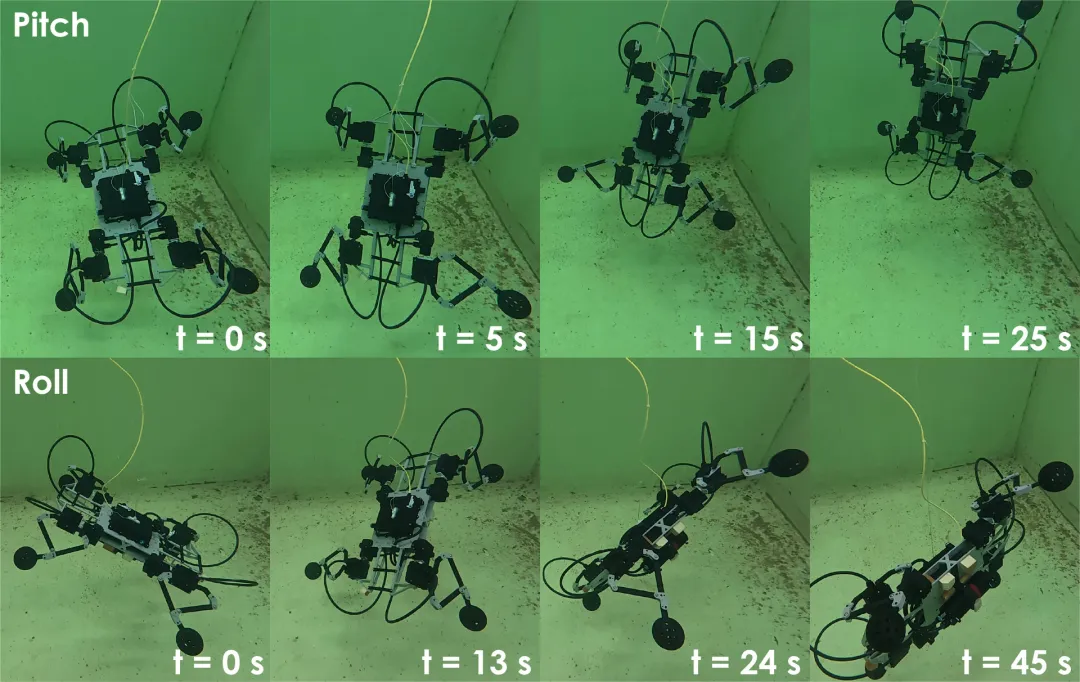
“ The four-legged robot moves underwater with its four legs.
Four-legged robots are already quite capable of hitting the ground, climbing the stairs, going through the fields, walking through the cobblestone roads. But once the water falls, they are mostly "hypnotic".
A team from the Norwegian University of Science and Technology (NTNU) recently did an interesting thing: they built a quadruped robot that can go underwater, and without any propellers or specialized propulsion devices, with the ball's resistance to rolling in the water at the end of the four legs, it can adjust its roll, pitch, and yaw posture underwater.
More importantly, the robot is fully assembled with ready-made, low-cost parts and is open source.
01.
How do you get waterproof? Put every motor in the hard drive.
The most painful thing about getting a land-based robot to water is that it's not a control algorithm, it's a waterproof pump, especially for those low-cost pumps that aren't designed for the ground.
The team adopted a hard drive scheme based on traditional ROVs (underwater remote control robots): each electronic component is placed in a rigid sealed outer shell. Specifically, each motor shell is made of two halves of POM (poly-methane) plastic processed together with bolts, forming a static sealed O-shaped circle that can be bought on the market in the middle of the shell.
Each leg is driven by three sealing machines. There is a clever design here: the control legs are driven by two "side-to-side" motors stretched along the arrow, a set of flat five-linked rods and joints, so that the two motors can fit into the same casing, and one leg requires only two sealing rods.
Each sewing machine drives a custom stainless steel shaft that extends into the water, forming a rotating joint. The shaft is mounted with a lip-like seal to prevent it from entering the water when it turns, and the side bearings are responsible for absorbing the path to the load, protecting the sealed lips from wear. The cable is pulled through BlueRobotics's WetLink passenger.
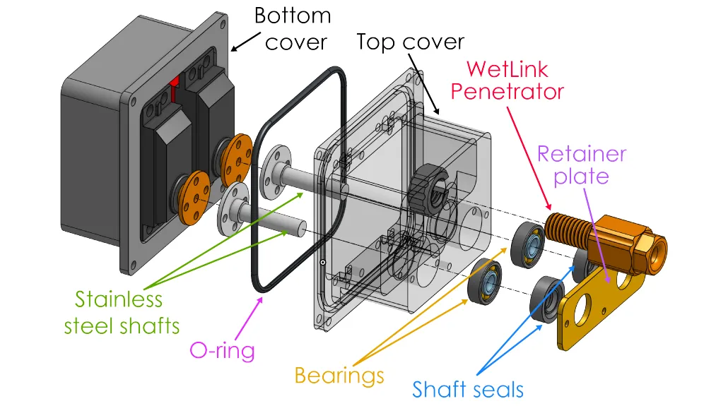
The team first performed a vacuum test and then drilled the robot into 1.5 meters of water for two hours, during which time the crankshaft continued to sweep all the way back and forth, ultimately detecting no water entry.
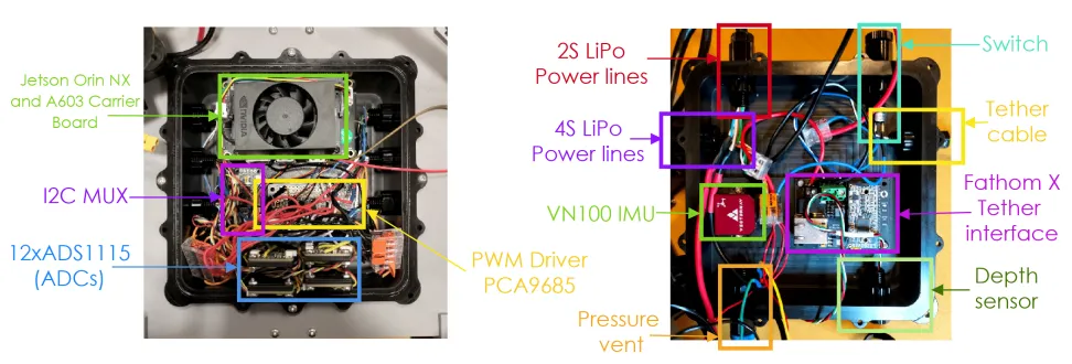
The main control panel follows the same sealing principle, with Jetson Orin NX, VectorNav VN-100 inertial measurement units, PWM drives, 12 ADCs, etc., and a total of 14 WetLink transceivers to insert each cable.
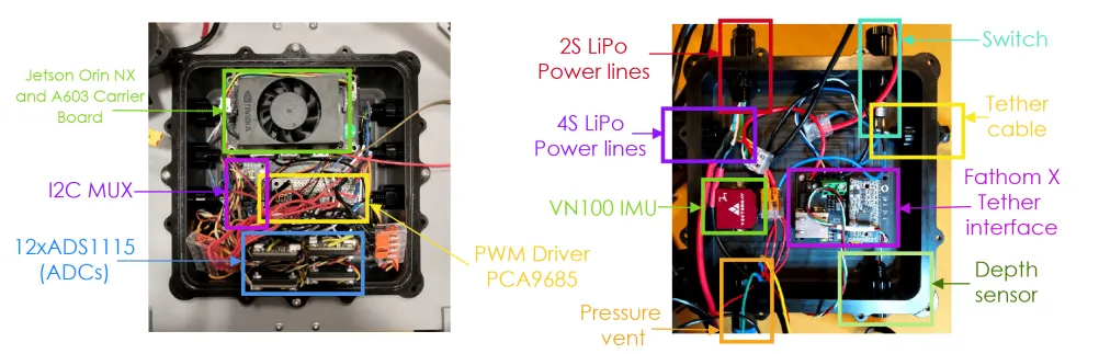
The overall size is approximately 58.99 x 34.44 x 15.33 cm and weighs 4.9 kg. The robot also has bubble blocks underneath, which are designed to bring the core and core as close as possible while allowing the overall slightly negative buoyancy so that it does not float on its own. All 12 joints are used by the AGF-RC's IB53BHU cylinder, a low-cost existing RC cylinder, which provides 3.9 Nm of torque and 95 rpm of torque.
02.
The key to that "hole-in-the-ball": relying on resistance as a propeller
The robot's most central idea is to use the ball at the end of the leg as a "water drill".
Because the hydrodynamic characteristics of the ball are that it does not generate lift, and the resistance is only related to the speed of motion and cross-sectional area, which greatly simplifies the mathematical modeling. The ball is 7.5 cm in diameter, is hollow, the surface is uniformly distributed through holes, which can increase resistance and not bring asymmetrical force, but also gradually reduce floating force.
In principle, when a leg ball moves rapidly in water, the water resistance acts on the ball, and this force is transmitted through the structure of the leg to the body, becoming the force that the rotor rotor robot on the body turns on, turns up and turns on.
In order to describe the entire system, the team specifically avoided the complex path of modeling complete hydropower. In principle, rigorous hydropower processing requires the estimation of additional mass and resistance coefficients for each component that moves in water, and the engineering is enormous. Here the researchers simplified: ignoring the added mass, but also ignoring the dynamics of the legs themselves, retaining only the resistance and momentum produced by the endpoints.
03.
The gesture controller on SO(3): how to move the force matrix "translate" into a foot
The team built a set of closed-loop gesture controllers based on SO3 (special 3-dimensional positive-intersection groups), which are entirely PID structures, with anti-pointer brackets and mechanisms.
Its workflow can be understood as three layers. First, based on the difference between the current gesture and the target gesture detected by IMU, the advantage of calculating a gesture error curve on SO 3 is that this method of representation avoids the peculiar problem that the curve of a curve will "dead" at a specific angle. Second, the PID control law calculates the total torque required by the body based on the error, while taking up the torque of the torque and the torque of the torque as a compensation for the forearm. This total torque is also limited to 2 Nm.
The third layer is the most interesting, called allocation: dividing the required torque by an average of four legs, then reversing how fast the ball at the end of each leg should move, in which direction, and finally converting it into the angle of each rotor by reverse motion.
However, the real system has two constraints: each leg's working space is limited, and a section must be recovered; and the position-controlled milling machine's bandwidth is limited and does not follow the instantaneous instructions. For this purpose, the team divides the four legs into two groups of opposing legs (1, 2) and (3, 4) so that they alternate for "strength thrust" and "recycling thrust".
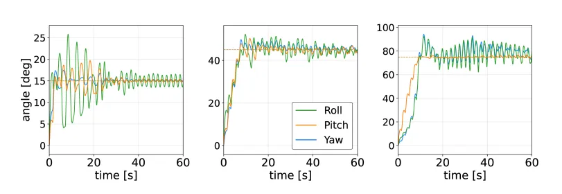
Before the official launch, the team verified the simulation using MuJoCo's fluid model based on inertia, with the ball's resistance coefficient CD = 0.64 (calculated through CFDs).
04.
Underwater tests: rolling, tilting, combined movements are stable
The actual experiment was carried out in the tank. The robot was attached to a fixed drawer shelf by means of a hook suspended on floating bubble blocks, so that it could both bind it to a fixed depth and reduce the strain of the rope interfering with the posture.
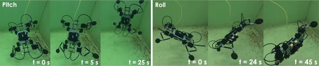
The team conducted three groups of experiments: the first group set the rolling values separately, from 15 to 90 degrees each; the second group measured the same tilt; the third group simultaneously gave the combination instructions for rolling and tilting 30 or 45 or 60 degrees. And each deviation angle started from a different initial position (ranging from 78 to +123 degrees), so "drawing the deviation back to zero" was always part of the control task.
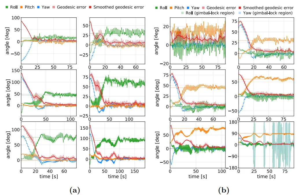
In rolling experiments, the greater the set value, the longer the time required to stabilize. In tilting experiments, the 75° and 90° angles required that the recovery time be shortened to 1.0 seconds in order to stabilize; and a phenomenon was observed in both groups: robots would temporarily "turn upside down" after being silently uplifted. This is because several legs enter a phase coupling that is unfavorable to generate torsion, after which the asymmetry of the workspace causes each leg to terminate at different times, breaking this mismatch and returning the legs to a more coordinated state.
In combined experiments, robots also stabilized near three settings of 30, 45, and 60 degrees.
The team also frankly pointed out the current limitations: the performance is mainly limited to speed. Due to the lack of more precise leg phase coordination, there is sometimes a situation where several legs enter the recycling phase simultaneously, causing a short interruption of torque and prolonged stability; in addition, the leg always shrinks back to a fixed position near the center of the workspace during recycling, resulting in about half the available travel per power stroke. These are all subsequently improved, thus making the robot more "agile" direction.
Overall, this work demonstrates one thing: Powered by hydropower resistance at the end of the sphere, coupled with a SO3 controller based on a simplified model, it is enough to allow a low-cost, replicable four-legged robot to complete gesture control underwater. The study was funded by the Norwegian Research Council through the Norwegian Centre for Intelligent Bodybuilding.
The following is the text of the paper: