And he took an empty bottle, and breathed into the mouth of the bottle, and said, Howl.
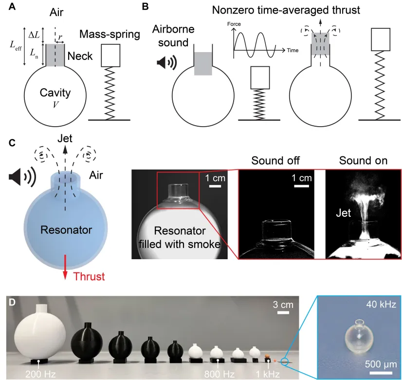
This is a trick that many people played as children, and it is the physical principle behind which Tom Hodges wrote a paper in 1860: the air in the bottle oscillates back and forth, the air in the bottle cavity is like a spring, the air in the bottle is like a mass block, and it forms a standard mass-spraying system.
Now a new breakthrough has been made by the EFFL research team based on this physical principle, and the results of the research have recently been published in the internationally renowned journal Science Advances.

They printed the bottle in 3D to a size of only a few hundred micrometers, and then sounded it "blowing".
The size shrinks from one centimeter to one micrometer, and the force shrinks from one millimeter to one micrometer.
The final result was two aircraft: one weighing 150 micrograms, with a weight of 4.9; the other weighing 184 micrograms, with a rotational speed of 13,000 rpm on its own.
01.
A bottle-blowing old physics was reworked into a propeller
Let's start by explaining why this is worth doing.
The path of micro-robots driven by sound waves has been traveled in liquid for many years, with tiny bubbles, sharp edge structures, sound flows, and all sorts of games. But in the air, acoustics are basically used only as "sound suspended": to place small objects in half-space by standing on waves or parallel lines.
The problem is that the sound suspension can hold something, but it cannot drive the machine. It depends on the sound radiation and the sound pulse, limited to the acoustic contrast factors (i.e. the density and compression difference between the object and the air), the force that can be given is small, and the shape of the suspension changes the effect.
Tom Hodgson's resonance travels a completely different path. The resonance frequency is determined by cavity volume and hip geometry:
f = (c/2π)·√(A/VL_eff)
Where c is the air speed (about 343 m/s at 20°C), A is the area of the neck, V is the volume of the cavity, and L_eff is the effective amplitude (physical amplitude plus edge correction of about 0.6r).
The smaller the volume, the higher the frequency. The research team printed an entire set of resonant cavities, covering 200 Hz to 40 kHz, using the four processes of fusion fusion deposition (FFF), light solidification (SLA), digital light processing (DLP) and double-photon polymerization (TPP).
The key question is: what does push have to do with it?
The team put the fluorescent cavity into the silencing chamber to measure the thrust with a precise telescopic scale called "superficial weight", while monitoring the sound pressure in real time with a microphone.
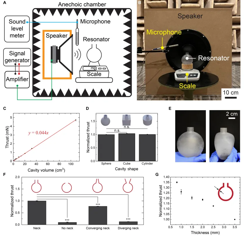
The results show that the force and volume of the cavity are strictly linear, with an inclination of 0.044, R2 = 0.999. The converse is 130 dB at sound pressure, and the volume of the cavity increases by 1 cm3 and the force increases by about 44 μN.
The shape of the cavity hardly affects the thrust. The thrust given by the three cavities of the sphere, cube, and cylinder is quite close to the cylinder because the size of the cavity is much smaller than the wavelength of the sound waves (kL << 1) and the shape itself is not important. This leads to a very practical hypothesis: it is possible to magnify the thrust with the array of cube cavities and test the thrust linearly with the number of arrays.
E = 64 GPa, PLA = 2 GPa, elasticity = 5 MPa, and the latter two are lighter and heavier than the other two.
What's really important is the neck.
There is a significant decrease in the thrust of the cavity of the cavity without the neck; the diameter of the cylinder is better than the inclination and expansion; the wall thickness is reduced from 3.5 mm to 0.75 mm, and the thrust is increased by about 35%. Further disassembly, the change in the thickness of the cavity wall is almost unaffected, and the change in the thickness of the neck significantly changes the thrust.
Incidentally, there is also a discovery at the process level: the same design at 300 Hz resonance chamber, the SLA print version is 1.4 times more powerful than the FFF version, and the Q value is higher (both 8.9 and 12.2), respectively. The print quality itself is the performance parameter.
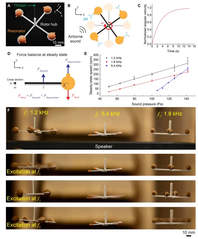
As the most basic mechanical component, the team made a turn: four 1.2 kHz millimetre oscillating cavities mounted on a 3D printed outline, suspended with a line.
The nice thing is that the single-hole thrust from the simulated airflow resistance counter is 70.4 μN and the Tianjin test is 71.9 μN. That is, this rotary machine can be designed entirely from the principle of first sex.
Then there's frequency selectivity: 1.2 kHz, 1.8 kHz, 5.4 kHz, three rotors are placed together, and then there's motivation, each rotation, without interfering with the other.
02.
Robots that will pilot ships: Trumpet Extrusion and Self-Driving Madha
With a propeller, the next step is to install it on the robot.
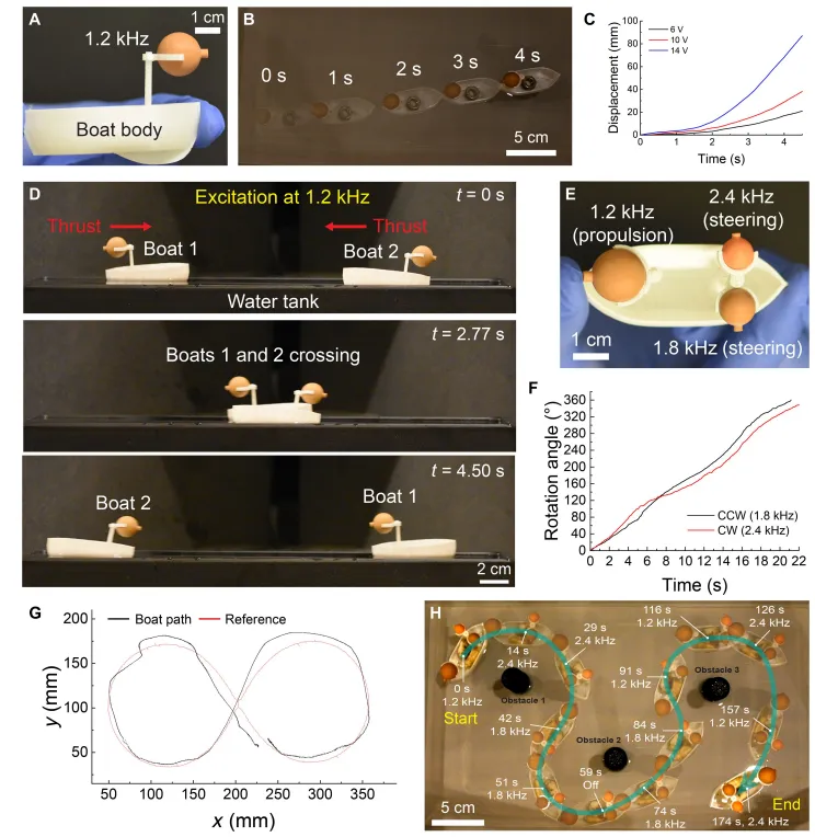
The first version was the "external version" small ship. The ship was equipped with a 1.2 kHz resonance chamber and a propeller when loaded. At 1.2 kHz, the ship began to move forward; adjusting the horn's input voltage, the shifting curve became steeper and steeper, indicating that the acceleration did increase with the sound.
There is a question that must be answered here: Is this the thrust of the horn cavity, or is it the direct sound radiation of the horn that is propelling the ship?
The team made two sets of controls. Two similar boats were positioned head-to-head with the same 1.2 kHz stimulation, moving in the opposite direction at the same speed; the one with the cavity and the one without the cavity were put together and the one without the cavity was completely motionless.
The conclusion is clear: the radiation from the horn can be ignored.
This property is very valuable. It means that multiple robots can be driven simultaneously by a single sound wave, whereas the direction of motion is determined by the direction of the oscillating cavity, rather than by the sound source. In contrast, magnetic drive: magnetic poles in the same magnetic field tend to move in parallel directions, requiring extreme difficulty in their movement, usually due to geometric differences, magnetic differences, or complex external magnetic field generators.
The team also fitted two ships with complementary cartridge structures to allow them to travel in a straight line, tied together to form a Swiss flag.
The true remote-operated version has three oscillating cavities: 1.2 kHz forward, 1.8 kHz counterclockwise, and 2.4 kHz counterclockwise. The two rotational frequency matches differ in thrust (about 15 μN and about 5 μN), so the rotation speed also varies slightly, with 17°/s and 15°/s.
At the bottom of the tank, a reference line with an "infinity symbol" is attached, which remotely controls small boats running along the line, averaging 5.70 mm of tracking error and 17.39 mm of maximum error.
So the team asked a question: What if the switch was placed directly on the cavity?
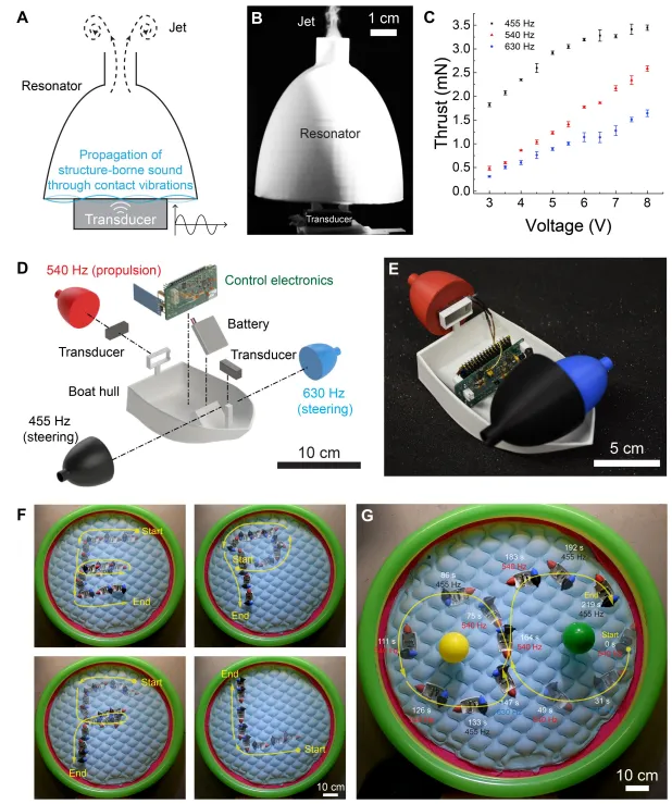
The result is possible. Structural sound propagation can also stimulate Tom Hodgson's resonance, provided that the switch is placed on a plane perpendicular to the neck axis.
On the power adapter model, the team compared the centrifugal magnetic field, pressurized electrophones, sound circuits and linear resonance stimulators (LRA), and finally selected the LRA, with an effective working range of 230 tonnes to 700 Hz. Accordingly, it printed 455, 540, 630 Hz three wavelength cavities, with the thrust corresponding to the linear increase of the driving voltage, the magnitude and the air sound stimulation.
There is also an additional surprise: using a branch-shaped waveguide to connect the four oscillating cavities, a single energy converter can drive simultaneously, bringing the total thrust closer to the individual stimulation of the four cavities.
The complete wireless mini-captain is as follows: 3D printed hull, three oscillating cavities ((540 Hz propulsion, 455/630 Hz rotation), two LRAs, a lithium-polymer battery, plus an automated PCB.
In the demonstration link, the ship's trajectory is written with four letters "EPFL", and the two balloons are rounded with four circles of infinite-shaped obstructions, with zero collisions. The researchers even suggested blowing the air, rearranging its posture after being deflected, and continuing to run on the intended route.
04.
150 micrograms takeoff and 13,000 turns per minute
The smaller the business, the more obvious the advantages of the scheme.
There are two reasons: one is that ultrasound wavelengths are short, and the focal size can be compressed to millimeters or submillimeters, which can accurately give a single trigger "hot" energy; and the other is that ultrasound is outside the range of human hearing and can reassure high power.
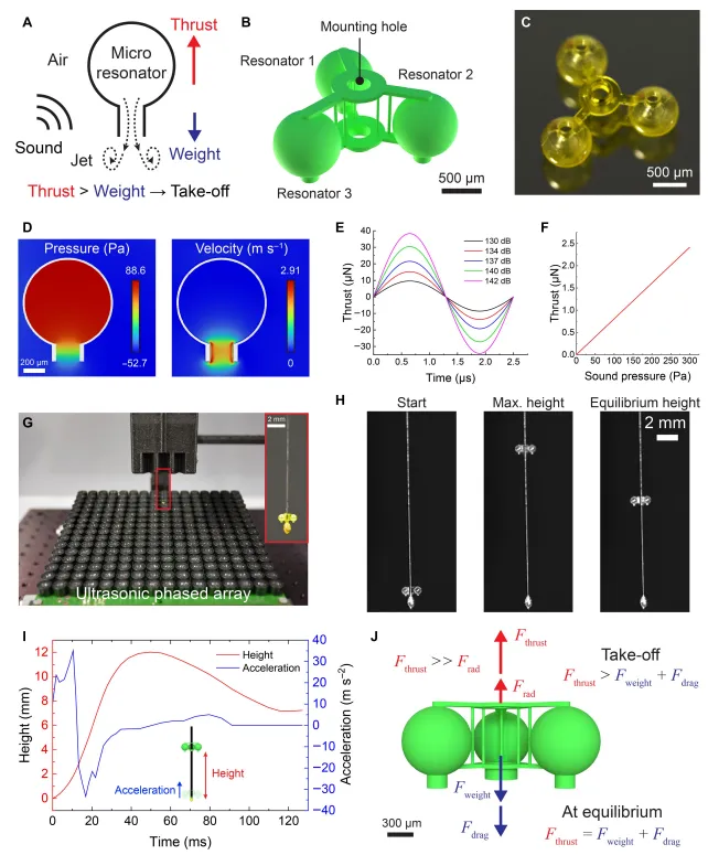
The first aircraft consisted of three 40 kHz oscillating cavities plus a lightweight frame, with a double-disc center hole, weighing about 150 micrograms, or 1.47 μN, and was printed with a dual-photon polygon.
The thrust was too small to be directly stated, and the team used numerical simulation: the sound stimulated a noticeable pressure accumulation inside the lower cavity, pressure gradients formed on both sides of the neck, driving a concentrated high-speed radiation flow.
The drive platform is a self-contained 16×16 phase control panel with a total of 256 40 kHz switches, focused at 3 cm above the forehead. The detection focus area has a sound pressure of about 300 Pa, corresponding to a single chamber thrust of 2.4 μN, with the three chambers combined weighing about 4.9.
The flight process was as follows: the sound wave was pulled off at a speed of about 30 m/s2 in 10 ms, pulled up to about 12 mm, and then slightly receded, stabilizing at about 7 mm. At this altitude, the sound pressure was tested at 85 Pa, the three-hole thrust was calculated at 1.9 μN, and a weight of 1.47 μN near the torque balance of the cylinder, and the thrust estimate was verified.
Concerning "is the sound radiation on it", the team gave the same contrast: spheres of the same quality as the same material did not react at all in the same sound field, the radiation energy calculated was only a few nanos, three quantum degrees less than the thrust; put the flyer back and forth, and it didn't move.
The second aircraft changed its mind: instead of relying on vertical radiation flow, it turned around to generate airborne lift.
Each of the three cylindrical cavities bears a sheet, symmetrically mounted on a double cylindrical cylinder, with a total weight of 184 micrograms, and a disc radius of 3.36 mm. The sheet uses a more favorable pressure distribution with a circular arc-shaped downward slope, a slower tail edge, and a Gurney tail edge, which increases the lifting force coefficient in the wide angle of attack, with only slightly increased resistance, and the best lifting resistance appears at about 20° angle of attack.
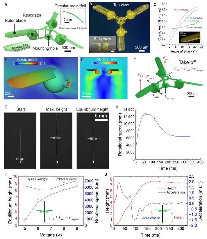
The test speed rapidly bounces to about 13,000 rpm after activation, then rises and falls to about 6,500 rpm with altitude. The peak gain is about 1.2. Interestingly, the equilibrium altitude under different driving voltages varies, but the steady-state speed almost does not change because it always only needs to compensate for its own weight.
The reverse positioning does not take off as well, again excluding the possibility of radiation-dominated.
The team also planned an unusual trajectory using a thin wire of 30 μm in diameter, allowing the aircraft to fly along the wire through a moving sound focus.
In the end, it was completely unrestricted free flight. Both types of aircraft could take off, but performed differently: the vertical-ray jet version took off, climbed fast, but occasionally flipped in flight; the rudder version was much more stable. The team speculated that the gyrotonic effect of high-speed rotation helped maintain posture, as did helicopters and disc toys.
By the way, a comparison number is mentioned: a magnetic-driven aircraft of the same size, weighing three times as much as the microplane here. This scheme is basically non-selective material, and can work with elastic modules ranging from a few MPa to tens of GPa, the only hard requirement being a resonant vacuum inside the tank.
Address of the paper: